Sorry for the delay. Rip it out and start again means you would have to change the HU and buy a new one.
However my first set of instructions may help you out.
I have managed to find the correct information and pictures to allow European owners to modify their radios and add an Aux In.
This is a copy of a post I made on the
www.My350Z.com website, this post is a combination of a number of posts on the first page which were missing their pictures, I found someone who had these pictures and have made a single post.
************************************************** **
1. Remove the dash and take the head unit out of it.
The guide here:
http://liljerk.morpheus.net/350Z/ is excellent (thanks my350z.com).
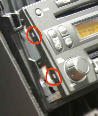
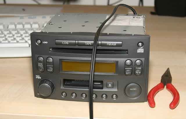
2. Remove the front (plastic) panel of the head unit.
It is held on by little clips all around perimeter. You can see two of them in this shot which was taken when I was testing to see if it worked. There are two on each side and three at the top and bottom. Slide a small screwdriver in between the plastic and the metal, gently lever the plastic up from the clip and slide a thin piece of card between the two to allow you to tackle the next one.
All clips done the front panel and the PCB that holds all the front panel controls should come off without much force (if you have to force it, some of the clips aren’t loose)
3. Remove the (perforated) bottom of the head unit.
It is held on by four small Philips screws through the bottom panel, two screws through the back and two screws through the front. All these removed carefully lever the bottom panel off at each side (at the join line) it will take a little force as there are some friction clips built into the side and (I think) the front.
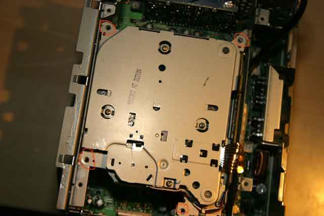
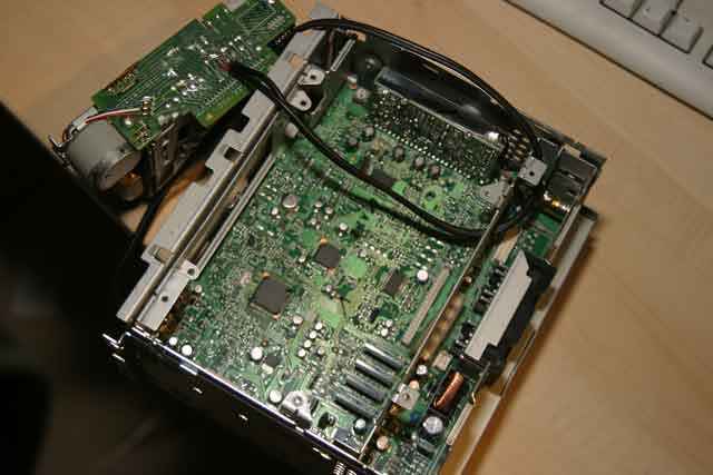
4. Remove the cassette unit.
The cassette unit is now sitting right in front of you. This picture was taken while I was reassembling the head unit but shows where the four screws that hold the cassette unit in are (they’re removed in this picture). To take the cassette unit out just remove these four screws and lift the unit vertically upwards.
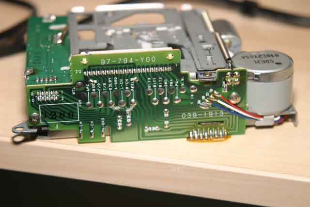
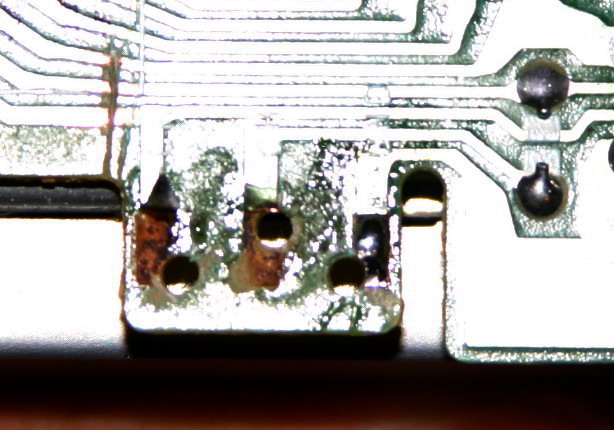
5. Find the correct PCB traces and break them.
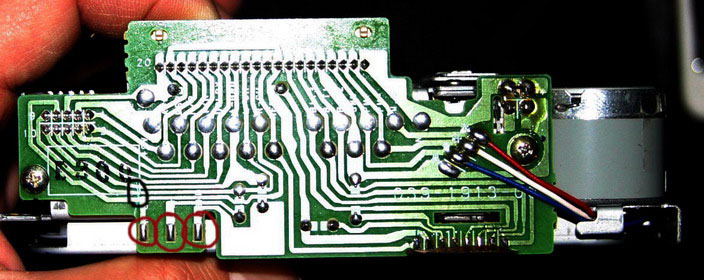
If you cassette unit looks like mine the back will look like this. The part sticking up (with 97-794-Y00 written on it) is the connector that plugs into the main PCB.
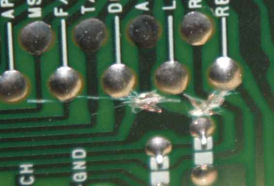
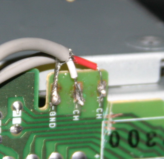
This picture shows how helpfully the PCB identifies what trace carries what signal. We need to break the traces for the Left (L-CH) and Right Channels (R-CH) plus the Audio ground (A-GND) upstream of the solder blobs (we will use those blobs to attach a cable to). You can break the traces by just scraping through them with the tip of a knife or some other sharp object (a jewellers screwdriver is ideal). You can see where I’ve done this in this closeup (note that I was a bit careless and let the knife slip a little).
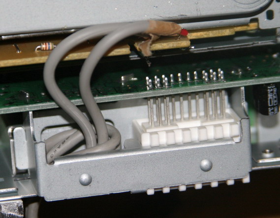
6. Attach a line out lead to the cassette unit PCB.
I just used a cheapo phono patch cord and cut one end off it. Carefully strip the cable. Wind the braided sleeves from the left and right channels together and tin them with a soldering iron. Strip the insulation off the left and right signal leads and tin those also.
It is easier to keep the leads about one inch long at this stage. You can cut them to the correct length now (for the A-GND lead) or after you’ve soldered them in position (for the L-CH and R-CH signal leads). It is very easy to attach the leads to the solder blobs on the cassette unit PCB as long as you’ve tinned them properly and everything is clean (I find a tiny amount of plumbers/corrosive flux aka soldering paste helps but you must clean any residue off the PCB when you’ve finished)
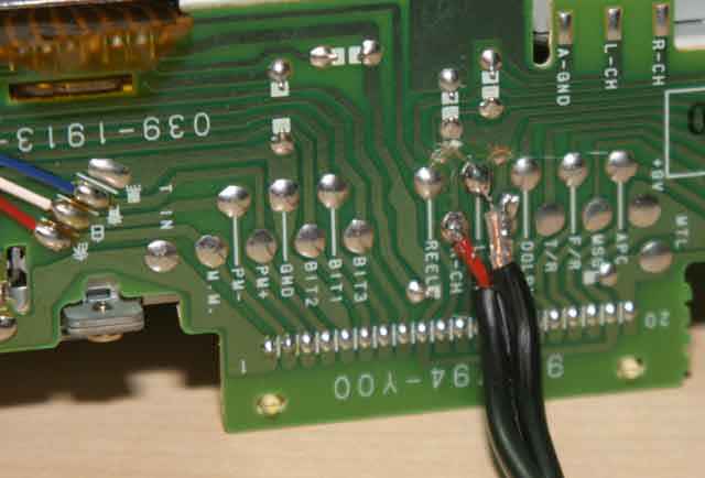
Here is a picture of the cassette unit with the line out attached.
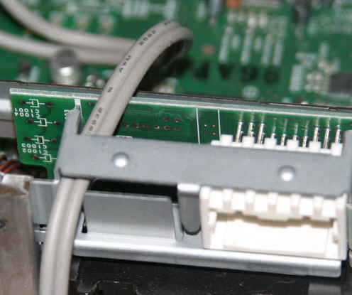
7. Threading the cable out the back of the headunit
If you used a cheapo patch lead like me the plugs should be small enough to feed through the various holes in the metalwork. If you used some nice shiny audiophile leads with big plugs my apologies because I should have warned you to feed the cable through first before you soldered it in place.
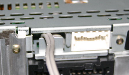
There is a metal bulkhead just behind the cassette unit This has a suitable hole on one side. You can see the cable fed through it here (this picture is taken with the satellite board that contains the Nav interface removed for ease of access. It is attached with two screws at the back, you’ve already removed the right hand one to get the bottom off).
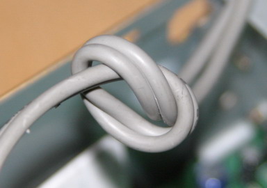
And there is a hole in the back of my headunit covered by a sticky black plastic patch. Peel that off and feed the lead through it. Before you do it might be a good idea to put sort of strain relief in. I did this by just loosely knotting the cable just before it exits the case.
8. Reassemble everything
In the reverse order that you took it out; so:
Fasten the cassette unit back with the four screws
If you removed it put the Nav daughterboard back but don’t screw it in until you’ve put the bottom back on
Push the bottom plate back on and insert all screws (at this point fasten the Nav daughterboard back)
Carefully push the front panel back into place. It shouldn’t take much force and should make a nice click when it’s back in position.
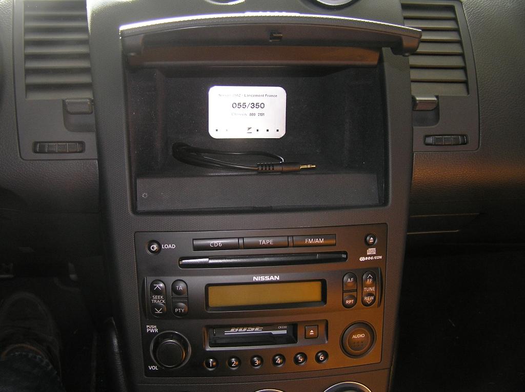
You should now have something that looks like this:
9. Testing and use
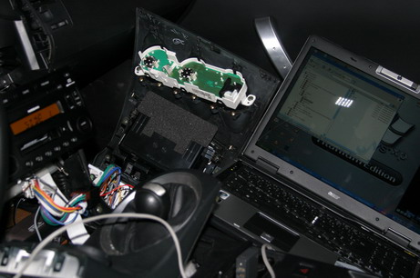
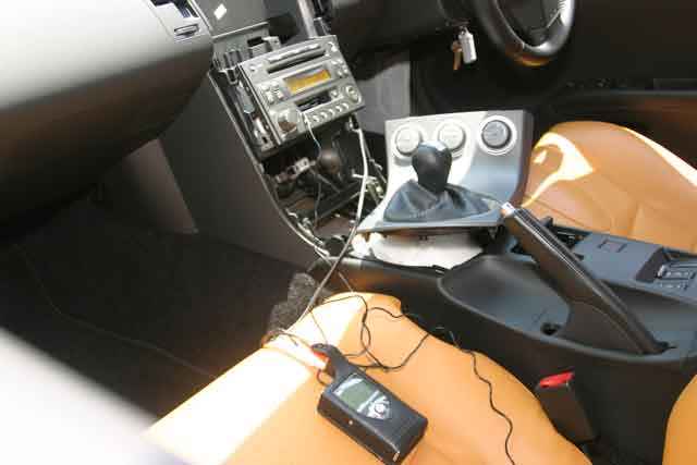
It is probably worth testing that it works before reassembling the dash. I didn’t have a wiring loom for the Bose outside of the 350Z so I just plugged it in and connected the phono leads to a portable iRiver MP3 player. Here is a picture.
Pressing “Tape” should now activate the line in. But you will need to fool the Bose into thinking that it is playing a tape (or nothing will happen). To do this I simply used a cassette adapter (one of the ones whose sound quality was so bad) with the input lead cut off (the picture is taken before the lead was given the chop, it’s not connected).
It worked perfectly with much better sound quality than either a tape adapter (whose signal has to pass through two tape heads a few amplifier stages and some equalisation to get it to the point where you’ve soldered the leads) or an FM modulator (I tried two, they were both lousy).
I was worried that the input would be very easy to clip and wouldn’t be able to handle line level signals. A definitive judgement will await the arrival of my OmniFi DMP1 MP3 jukebox, but in the test with the iRiver (which is an iPod clone) I wasn’t able to detect any obvious clipping even with the iRiver at very high volumes (at which point the line in was much louder than either radio or CD) so it seems to be useable.
10. Caveats/warnings
This seems to work for me; I don’t use cassette at all so sacrificing it was an easy choice to make. It is pretty easy process (actually getting the dash off was harder) but breaking the PCB traces probably isn’t easily reversible, so be careful. I don’t know what will happen if you cut any of the other traces.
This was done on a 2003 350Z in Singapore – if your Bose headunit is substantially different from the pictures or doesn’t have the helpful labels on each trace or you don’t feel comfortable taking it apart you might want to think about some other route.
Hope that this helps some people.
")
")
 et au volume nickel.